
User Interface and Navigation
Get familiar with the RabbitCAM X workspace, explore the Model, Machining, and Simulation tabs, and learn how to navigate the 3D view.
Workspace Overview
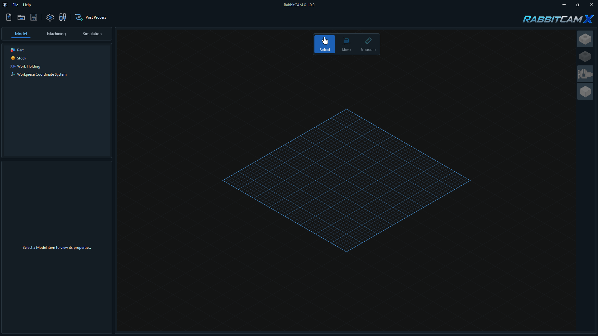
RabbitCAM X organizes your work into three main tabs: Model, Machining, and Simulation. These tabs follow the main stages of preparing a CNC project: setting up the model, creating machining operations, and reviewing the calculated toolpaths.
The left side of the window contains the project items and settings for the selected tab. The large area on the right is the 3D view, where you inspect your model, stock, work holding, and toolpaths.
The main toolbar at the top provides quick access to frequently used commands:
- New Project — start a new project.
- Load File — open an existing RabbitCAM X project or import a supported CAD file.
- Save Project — save your current project.
- Settings — open the application settings.
- Tools — open the tool libraries.
- Post Process — open the NC program generation window.
When you first open the application, the 3D view displays an empty grid. Load a CAD file or an existing project to begin.
The Model Tab
Use the Model tab to prepare the physical setup of your project.
The model tree contains four main items:
- Part — the CAD geometry of the component you want to machine.
- Stock — the starting material from which the part will be machined.
- Work Holding — models of fixtures, vises, or other components used to hold the workpiece.
- Workpiece Coordinate System — the work zero and coordinate system used for machining.
Select an item in the model tree to display its available properties in the panel below.
The floating toolbar near the top of the 3D view provides three tools:
- Select — select objects in the view.
- Move — adjust the position and orientation of a selected Part or Work Holding item.
- Measure — inspect dimensions and distances using the model geometry.
The availability of these tools depends on the loaded geometry and your current selection.
The buttons along the right edge control the display of the part, including opaque and transparent modes, and the visibility of the stock and work holding.
The Machining Tab
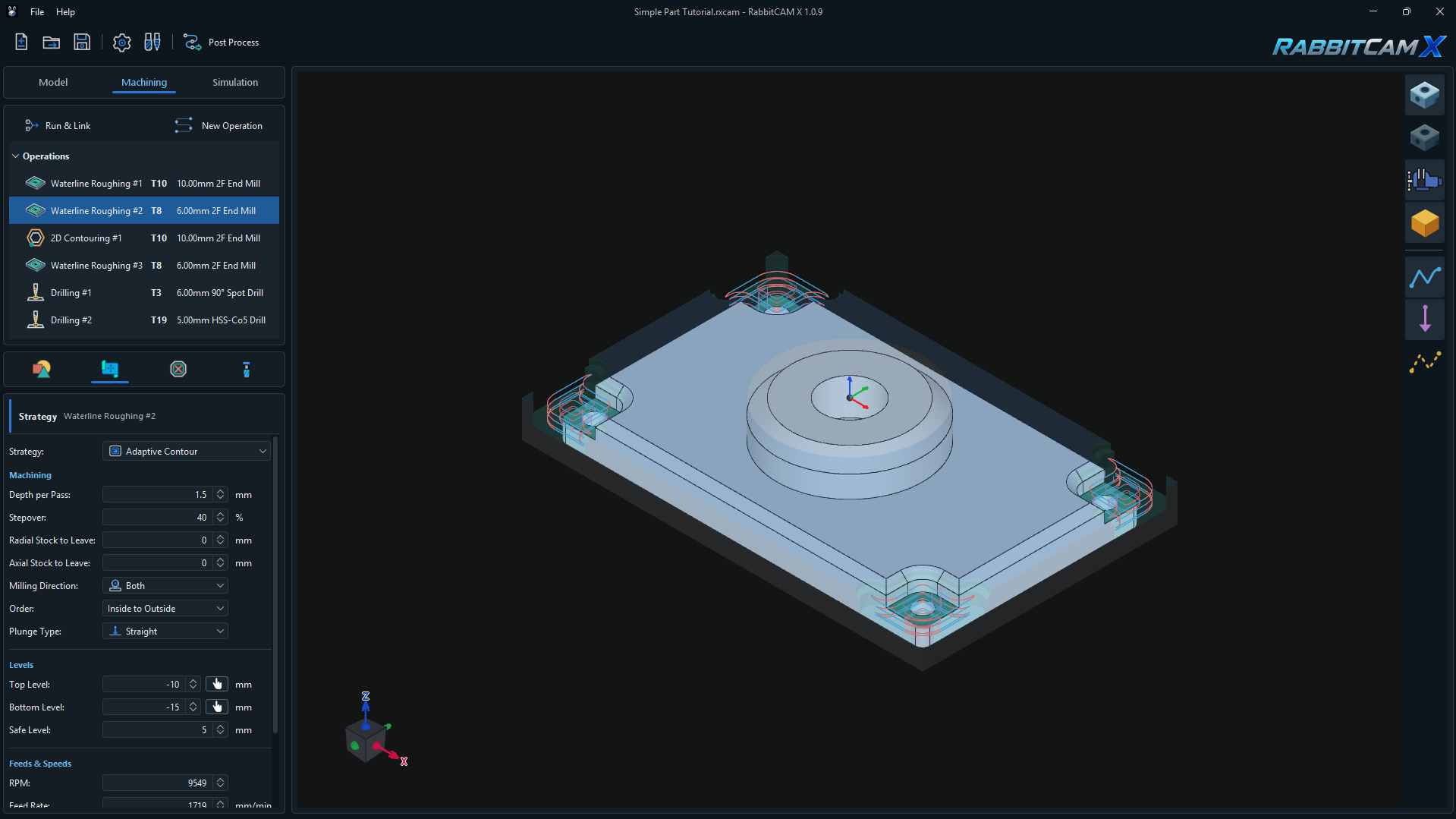
Use the Machining tab to create machining operations, configure their settings, and calculate the toolpaths for your project.
The Operations List
The Operations list appears in the upper-left panel. Each operation shows its name, tool number, and tool description. Select an operation to inspect its settings in the panel below. Select the Operations heading to display the calculated toolpaths from all operations.
Creating an Operation
Click New Operation to choose an operation type, give it a name, and select a cutting tool. After creating the operation, use the settings panel to define its machining geometry and parameters.
Operation Settings
The four icon tabs below the Operations list organize the settings for the selected operation. From left to right, they are:
- Job Assignment — choose the geometry that the operation will machine.
- Strategy — select the machining strategy and adjust its parameters, machining levels, feeds, and speeds.
- Restricted Areas — define areas to exclude from machining, where supported by the selected operation.
- Tool — review or change the cutting tool and its related settings.
The available settings depend on the operation type and strategy. In the example above, Waterline Roughing #2 is selected and the Strategy panel shows Adaptive Contour, together with settings such as Depth per Pass, Stepover, Top Level, Bottom Level, and Safe Level. Scroll down inside the settings panel to access additional parameters.
Calculating Toolpaths
Click Run & Link, or press Ctrl+R, to calculate and link the toolpaths for the project. Run it again after changing settings that affect the toolpaths, then inspect the updated result in the 3D view.
Inspecting the Result
The buttons along the right edge of the 3D view control the visibility of the part, stock, and work holding. Additional buttons show or hide the cutting toolpaths, plunge movements, and rapid movements (G0), helping you inspect each type of motion separately.
Use the Simulation tab to review the calculated machining sequence. When the project is ready, use Post Process in the main toolbar to generate the NC program for your machine.
The Simulation Tab
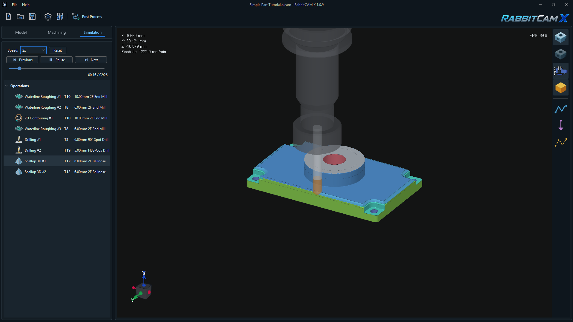
Use the Simulation tab to review the calculated tool movements and see how material is removed from the stock. Before starting, use Run & Link in the Machining tab to calculate the toolpaths. Recalculate them after changing settings that affect machining.
Choosing What to Simulate
The Operations list appears below the playback controls. Select the Operations heading to simulate the complete calculated program, or select an individual operation to focus on that stage of the project.
When you select an individual operation, the simulation starts with the stock remaining before that operation. This lets you inspect how it continues the machining work performed by earlier operations.
Playback Controls
The controls at the top of the left panel let you play the simulation continuously or inspect individual tool movements:
- Play / Pause — start or pause playback. The button changes to Pause while the simulation is running.
- Previous — pause playback and return to the start of the current tool movement. If you are already at its start, move back to the start of the preceding movement.
- Next — pause playback and advance to the end of the current tool movement.
- Reset — pause playback and return the selected simulation to its beginning, restoring its starting stock state.
- Speed — choose the playback speed. Use a lower multiplier to inspect detailed movements or a higher multiplier to review the sequence more quickly. This setting controls simulation playback; the programmed feeds and speeds remain unchanged.
Timeline and Time Display
The timeline slider lets you move to a particular point in the selected simulation. Drag the slider and release it to update the tool position and remaining stock at that time. Playback pauses when you use the slider; click Play to continue.
The time display below the slider shows the current simulation time followed by the total simulated duration for the selected operation or complete program.
Inspecting the 3D View
The 3D view displays the cutting tool and the stock as machining progresses. The readout in the upper-left corner shows the simulated tool position along X, Y, and Z, together with the feedrate.
Use the buttons along the right edge to control the part display and the visibility of the stock, work holding, cutting toolpaths, plunge movements, and rapid movements. Rotate, pan, and zoom to inspect the result from different angles.
Pause at areas you want to examine more closely, check the sequence of tool movements and the material remaining, and return to the Machining tab if an operation needs adjustment. After recalculating and reviewing the result, use Post Process to generate the NC program for your machine.
Navigating the 3D View
Use the mouse inside the 3D view to inspect your project from different positions and angles.
| Action | Mouse control |
|---|---|
| Rotate the view | Hold the middle mouse button—the scroll wheel—and drag. |
| Pan the view | Hold the right mouse button and drag. |
| Alternative pan control | Hold Shift and the middle mouse button, then drag. |
| Zoom in or out | Scroll the mouse wheel. |
Rotating, panning, and zooming change your viewing position. Use the Move tool when you want to change the actual placement of a supported project item.