Setting the Workpiece Coordinate System
Set the G54 work zero using coordinates, stock and part presets, or points picked from the CAD geometry, and check the origin before generating toolpaths.
Understanding the Work Zero
The Workpiece Coordinate System defines the reference point used for machining coordinates. RabbitCAM X displays this work coordinate system as G54. Its origin is the point that represents X0 Y0 Z0 in the machining setup.
Choose a reference that you can also locate on the physical workpiece, such as a stock corner, the center of the stock, or a feature on the part. Set the corresponding G54 work zero on your CNC machine when preparing the job. Setting the origin in RabbitCAM X configures the CAM project; it does not set the machine's work offset.
Complete the stock dimensions and part placement first. See Setting Up the Stock and Part Position.
Viewing and Entering the Origin Coordinates
- Open the Model tab.
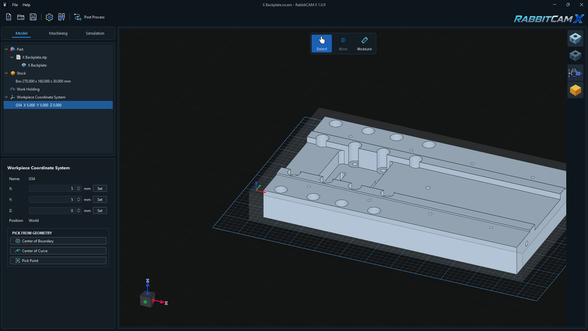
- Expand Workpiece Coordinate System in the model tree and select its G54 item.
- Review the X, Y, and Z fields in the properties panel. These values locate the work zero in the project's World coordinates, in millimeters.
- Enter a coordinate and commit the field, or use its spinner arrows. The origin updates as the field value changes.
- Check the origin marker in the 3D view and the updated G54 entry in the model tree.
In the example above, the origin is at X = 5 mm, Y = 5 mm, and Z = 0 mm in World coordinates. That point becomes X0 Y0 Z0 in work coordinates. These are example values for this project.
The Position: World label describes the reference used for the displayed coordinates. Changing the origin leaves the part and stock in place. The work axes remain parallel to the World axes.
Using Stock and Part Presets
Click Set beside an axis to choose a coordinate from the current stock or part bounds. Each Set menu changes only its own axis and keeps the other two coordinates.
- Stock Min, Stock Center, and Stock Max use the minimum, midpoint, or maximum of the stock bounds along that axis.
- Part Min, Part Center, and Part Max use the corresponding bounds of the complete part.
Center means halfway between the minimum and maximum coordinates along the selected axis. It is the center of the bounds, which may differ from the center of a particular feature.
For a box stock origin at the top corner where X and Y are smallest, choose:
- X > Set > Stock Min.
- Y > Set > Stock Min.
- Z > Set > Stock Max.
For an origin at the center of the stock's top face, use Stock Center for X and Y, and Stock Max for Z.
Presets use the geometry at the time you select them. After changing stock dimensions or moving the part, review the origin and apply the required presets again.
Picking the Origin from CAD Geometry
The PICK FROM GEOMETRY controls let you place the origin using a feature in the 3D view:
- Center of Boundary — click an edge belonging to a closed CAD boundary. RabbitCAM X uses the center of that boundary's bounds.
- Center of Curve — click a CAD curve to use the center of its bounds.
- Pick Point — click a CAD vertex, such as a model corner or an edge endpoint, to use that point directly.
Click the required button, move over the geometry in the 3D view, and select the intended feature. An accepted pick updates all three origin coordinates and ends the picking mode.
For the two center options, the center is calculated halfway between the selected geometry's minimum and maximum coordinates in X, Y, and Z. For a partial arc or an irregular outline, this may differ from the circle center or the area centroid.
Check Z after picking. To keep the selected X/Y location while placing zero on the stock's top face, use Z > Set > Stock Max afterwards.
If RabbitCAM X reports that the selected geometry center is outside the stock bounds, check the stock's X/Y extent and the part placement. If a feature cannot be selected, zoom in and select a suitable CAD edge, closed boundary, or vertex for the active picking tool.
Choosing the Z Reference
The Z origin determines which physical height is treated as Z0. Use Stock Max for Z when the top of the starting material is your reference, or Part Max when the highest point of the finished part is the intended reference. These heights can differ when the stock includes material for facing.
With a top reference and the normal positive-Z direction, positions below that reference have negative work Z coordinates. Review each operation's top, bottom, and safe levels against the origin you selected.
If you change Z after creating operations, RabbitCAM X adjusts most operation levels to preserve their model heights. Facing levels remain relative to the work zero, so review Facing operations especially carefully after changing the reference.
Checking and Saving the Coordinate System
- Confirm that the origin marker is on the intended reference point and that the X, Y, and Z values match your setup.
- Check the origin again after changing the stock or part position.
- If machining operations already exist, review their levels, use Run & Link to regenerate the toolpaths, and inspect the result in Simulation.
- Save the project with File > Save Project or Ctrl+S.
When preparing the CNC machine, use the same physical reference point and axis directions for the machine's G54 setup. After a CAM origin change, generate a new output file through Post Process so the machining program matches the saved setup.