
Setting Up Work Holding
Add STEP models of vises, clamps, and fixtures, position them around the workpiece, and include the work holding in your machining setup.
Understanding Work Holding
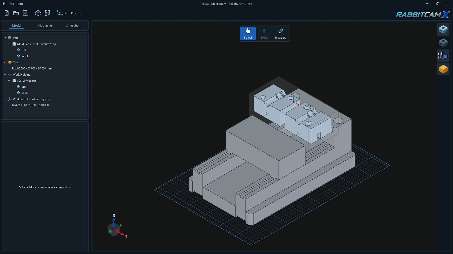
Work Holding contains the CAD models of the equipment used to hold your workpiece, such as a vise, clamps, or a custom fixture. These models describe the physical obstacles around the material during machining.
In the example above, the 80x100 Vice.stp file is listed under Work Holding, with its individual solids below it. The mold components remain under Part, and the starting material is defined under Stock.
Prepare the part and stock first, then add the fixture geometry and adjust its position to match the actual setup. For the preceding steps, see Setting Up the Stock and Part Position.
Adding a Work Holding Model
- Open the Model tab.
- Right-click the Work Holding heading in the model tree and choose Add.
- In Add Work Holding, select a STEP file with the extension .stp or .step.
- When the Work Holding Position window appears, choose how to place the imported model.
- Center aligns the center of the complete fixture's X/Y bounds with the center of the Part's X/Y bounds. It also places the fixture's lowest point at World Z0.
- Keep Original Position preserves the coordinates stored in the STEP file. Use this when the fixture was already positioned relative to the part in CAD.
- Cancel ends the import without adding the fixture to the project.
After import, the file and its solids appear under Work Holding. Repeat Work Holding > Add to include additional fixture files.
The Center option provides an initial placement. Check the fixture height, orientation, and jaw positions before continuing. World Z0 can differ from the G54 work zero chosen for machining.
Positioning the Fixture and Its Components
Select the item you want to adjust in the model tree:
- Select the Work Holding heading to move all imported fixtures together.
- Select a STEP file beneath it to move that complete fixture or assembly.
- Select an individual solid beneath the file to adjust that component, such as a separately modeled movable jaw.
- With the required item selected, click Move in the floating toolbar above the 3D view.
- Use the translation handles to change its position, or the rotation handles to change its orientation.
- Inspect the result from several angles and adjust the fixture to match the workpiece and stock placement.
- Return to Select when the adjustment is complete.
Select the complete file when you want to preserve the relative positions of its components. Select a child solid when you intend to change that component's position within the assembly.
How Work Holding Affects Toolpaths
Adding a Work Holding model automatically registers it as a physical obstacle for the project. These entries appear in the operation's Restricted Areas list with the label [Work Holding - Automatic].
RabbitCAM X uses the fixture geometry during supported toolpath generation. The automatic entries apply across the project and cannot be removed from an individual operation's Restricted Areas list. Hiding the fixture in the 3D view keeps its obstacle definition active.
Adding, moving, rotating, or removing Work Holding makes existing machining results require recalculation. Use Run & Link after changing the setup, then inspect the updated paths in Simulation.
If generation reports that an operation does not support Work Holding avoidance, or that an obstacle cannot be processed, review the reported operation and fixture geometry before continuing. Check access around jaws and clamps, clearance above the fixture, and the movements between cutting passes.
Showing, Hiding, and Removing Work Holding
Use the Render Work Holding button on the right-hand toolbar of the 3D view to show or hide the fixtures. This can help you inspect geometry that is obscured by the vise or clamps. The button changes visibility only.
To remove a fixture from the project:
- Right-click its STEP file under Work Holding.
- Choose Delete.
- Confirm the removal in the Delete Work Holding dialog.
This removes the selected file and its fixture solids from the project, together with their automatic obstacle definition. The original STEP file remains on disk. Regenerate the toolpaths after changing the fixture list.
Checking and Saving the Setup
- Check that the imported fixtures represent the equipment used for this job.
- Inspect the placement of the stock, jaws, clamps, and supports from several viewing angles.
- Review the Workpiece Coordinate System and confirm that the origin still matches the intended machine setup.
- Use Run & Link for existing operations and review the result in Simulation, with Work Holding visible.
- Save with File > Save Project or Ctrl+S.
The .rxcam project stores the Work Holding CAD files and their placement, so the fixture setup is restored when you reopen the project. After changing the setup and recalculating the toolpaths, use Post Process to create an updated machining program.
For origin setup, see Setting the Workpiece Coordinate System.