
2D Contouring
Machine profiles with Simple or Helical Machining. Assign contour geometry, choose the tool side, set machining depths and allowances, and check the generated toolpath.
2D Contouring Overview
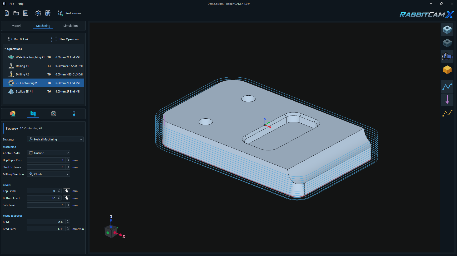
2D Contouring machines a selected profile through a range of Z levels. Use it for outside profiles, inside walls, or paths where the tool center must follow the selected contour.
The operation uses the contour's X/Y shape together with the Top Level and Bottom Level you specify. Selecting a surface provides a projected contour; it does not make the tool follow the surface's changing Z height.
The example above shows 2D Contouring #1 using Helical Machining and Outside, with T8 — 6.00 mm 2F End Mill. The toolpath descends around the external profile from Z0 to Z-12 mm.
Creating the Operation and Assigning Geometry
- Prepare the part, stock, and work zero, then open Machining > New Operation.
- Choose 2D Contouring under 2D / 2.5D Operations, review the name and assigned milling tool, and click Create.
- Select the operation and open Job Assignment.
- Open Pick and choose the geometry selection method.
- Select the required geometry in the 3D view and complete the selection with the matching Finish Boundary Selection, Finish Curve Selection, or Finish Surface Selection button.
- Review the assigned chains, then open Strategy.
The available selection methods are:
- Boundary — select a closed CAD boundary. This is a direct way to assign an outside or inside profile.
- Curves — build a chain from connected curves by clicking to extend the selection.
- Surface or Surfaces (Lasso) — select surfaces whose grouped X/Y projection defines the contour.
Use a continuous, closed profile for Inside or Outside compensation. Open paths can be machined with On Contour.
Choosing Simple or Helical Machining
Choose the cutting method from Strategy:
- Simple machines the contour at successive constant Z levels. Depth per Pass controls the vertical steps toward the final depth.
- Helical Machining gradually lowers Z while following a closed contour. For an uninterrupted contour, each circuit descends by up to Depth per Pass, with the final descent ending at Bottom Level.
Helical Machining automatically adds a constant-depth pass at Bottom Level to complete the bottom of the profile. This pass keeps the selected Stock to Leave allowance.
Open contours use constant-depth passes even when Helical Machining is selected. To obtain a continuous descending path, assign a closed contour. Obstacle avoidance can split a closed path into separate cutting segments with clearance moves between them.
Contour Side and Machining Settings
Contour Side determines where the tool center runs relative to the selected profile:
- Outside offsets the tool center outward from a closed contour.
- Inside offsets the tool center inward from a closed contour.
- On Contour places the tool center directly on the selected path, with no tool-radius offset. Account for the cutter width when checking the resulting cut.
For Inside and Outside, RabbitCAM X calculates the offset using the tool radius plus Stock to Leave. This allowance is radial material retained on the wall for a later operation. At 0 mm, no additional radial allowance is requested. The field is hidden for On Contour.
Depth per Pass controls the maximum vertical step. The screenshot uses 1 mm over a 12 mm depth range, producing twelve 1 mm descents before the final bottom-level pass.
Milling Direction offers Climb and Conventional. For compensated closed contours, it determines the travel direction around the profile. On Contour and open paths retain the selected geometry's direction.
Setting Top, Bottom, and Safe Levels
All levels are Z coordinates relative to the project's work zero:
- Top Level — the starting height for the depth range.
- Bottom Level — the final cutting height. It must be lower than Top Level.
- Safe Level — the clearance height for approach, linking, and retract movements. It must be higher than Top Level.
The screenshot uses Top Level = 0 mm, Bottom Level = -12 mm, and Safe Level = 5 mm.
Enter levels directly or click the pick button beside Top Level or Bottom Level and select a part surface. Top Level uses the selected surface's highest Z; Bottom Level uses its lowest Z. RabbitCAM X converts the result to work coordinates.
Check the values against the intended machining depth and the actual stock and fixture setup. For origin settings, see Setting the Workpiece Coordinate System.
Setting Feeds and Speeds
- RPM sets the spindle speed in revolutions per minute.
- Feed Rate sets the cutting feed in mm/min, including the combined X/Y/Z movement of a helical descent.
- Plunge Rate is shown for the Simple strategy and sets the feed for downward entry moves. The Helical Machining panel displays RPM and Feed Rate.
The example shows 9549 RPM and a Feed Rate of 1719 mm/min. These are the pictured project's values; choose settings appropriate to your tool, material, machine, and cutting engagement.
Part Protection and Work Holding
For Inside and Outside, RabbitCAM X checks the compensated paths against the part geometry. Imported Work Holding models are also included as physical obstacles. Blocked sections can be removed from the cutting path, with clearance moves connecting the remaining segments.
On Contour follows the selected centerline without the part-protection check used by Inside and Outside. Work Holding obstacles still apply. Inspect the cut and cutter clearance when using this mode.
The calculated clearance height can be raised above the entered Safe Level to clear the modeled obstacles. If no cutting segment remains at a depth, generation reports an error. Review the selected contour, tool diameter, allowance, and fixture placement.
For fixture setup, see Setting Up Work Holding.
Generating and Checking the Toolpath
- Click Run & Link to calculate the toolpaths.
- Select the 2D Contouring operation and check that the path follows the intended profile and tool side.
- Inspect the descent, final depth, bottom-level pass for Helical Machining, and any clearance moves.
- Open Simulation and review the resulting wall, remaining allowance, and access around fixtures.
- Recalculate after changing geometry, strategy settings, the tool, or the setup. Save with Ctrl+S and use Post Process when ready to generate the machining program.
If generation fails, check that at least one valid continuous contour is assigned, the tool is valid, Depth per Pass is positive, Bottom Level is below Top Level, and Safe Level is above Top Level. Inside and Outside also require a closed contour.