
Facing
Create a flat reference surface with the Facing operation. Set up the fixed Work Z0 cutting plane, configure ZigZag passes, and generate a toolpath across the stock.
Facing Overview
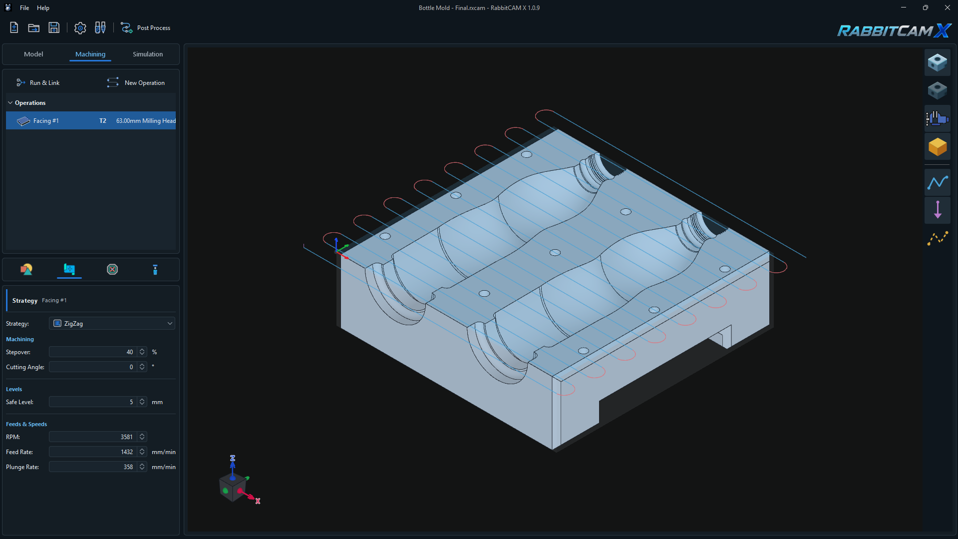
Facing creates parallel cutting passes across the stock to produce a flat reference surface. It uses the ZigZag strategy, with successive passes running in opposite directions.
The operation uses the stock's X/Y bounds to determine the area to cover. Its cutting plane is fixed at Work Z0, as defined by the Workpiece Coordinate System.
The example above shows Facing #1 using T2 — 63.00 mm Milling Head. The Strategy panel contains the machining, clearance, and feed settings described below.
Creating a Facing Operation
- Prepare the Part, Stock, and Workpiece Coordinate System in the Model tab.
- Open Machining and click New Operation.
- Under 2D / 2.5D Operations, select Facing.
- Keep the suggested name or enter a descriptive name for the operation.
- Review the assigned tool. Use the ... button beside the tool field to select a compatible milling tool when needed.
- Click Create, select the new operation in the Operations tree, and open Strategy.
Facing determines its coverage from the stock, so you do not need to pick part surfaces or boundaries for the Job Assignment. Confirm that the stock dimensions represent the material you intend to face.
Setting the Cutting Plane at Work Z0
Facing cuts at a single, fixed height: Z0 in work coordinates. The Strategy panel therefore has no Top Level, Bottom Level, or Depth per Pass field.
Place the work zero at the height of the intended finished surface. The amount removed is determined by the material above that plane. For example, if the top of the stock is at work Z+0.5 mm and the intended surface is at work Z0, the geometric facing allowance is 0.5 mm.
If the work zero is exactly on the stock's existing top surface, Facing runs on that same nominal surface. It does not automatically choose a lower cutting depth. The operation also does not divide the allowance into multiple depth passes; check that the planned removal suits the tool and setup.
Changing the WCS Z origin changes the physical height of the Facing plane. Recalculate the toolpath after adjusting it. See Setting the Workpiece Coordinate System.
Configuring the ZigZag Strategy
The Strategy selector displays ZigZag. Configure its passes using the following fields:
- Stepover — the spacing between adjacent passes, expressed as a percentage of tool diameter. The available range is 1–100%. A smaller value places the passes closer together. In the screenshot, a 63 mm tool at 40% stepover gives a nominal spacing of 25.2 mm.
- Cutting Angle — the direction of the passes in the X/Y plane. At 0°, the passes run parallel to X; at 90°, they run parallel to Y. Change the angle to suit the stock orientation and available approach space.
- Safe Level — the clearance height in work coordinates, above the fixed Z0 cutting plane. The screenshot uses Z+5 mm. Set it high enough for the stock and fixture setup.
The tool-center coverage extends beyond the stock edges so the cutter can pass fully across them. These extensions are expected; inspect the surrounding space and any work holding when checking the generated path.
Setting Feeds and Speeds
The Feeds & Speeds section controls spindle speed and feed movements:
- RPM — spindle speed in revolutions per minute. The screenshot shows 3581 RPM.
- Feed Rate — the cutting feed along the ZigZag passes, in mm/min. The example uses 1432 mm/min.
- Plunge Rate — the feed used to enter the Z0 cutting plane, in mm/min. The example uses 358 mm/min.
These values illustrate the pictured project. Choose the operating values for your actual cutter, material, machine, and amount of material being removed.
Facing Around Work Holding
Imported Work Holding models are included as automatic physical obstacles. Facing excludes the corresponding tool-center areas, accounting for the cutter radius, when generating its passes.
The generated clearance height can be raised above the entered Safe Level when needed to clear the modeled work holding. Check the resulting approach, linking, and retract movements in the 3D view and Simulation.
If the fixtures exclude the entire facing area, generation reports an error. Review their placement and the available cutting space. Hiding a fixture with Render Work Holding only changes its visibility; it remains an obstacle.
For fixture setup, see Setting Up Work Holding.
Generating and Checking the Toolpath
- Click Run & Link to calculate the toolpaths.
- Select the Facing operation and inspect the coverage, pass direction, and paths extending beyond the stock.
- Open Simulation and review the material removal, entry moves, links between passes, and final retract.
- If you change the tool, stock, work zero, work holding, or strategy settings, run the calculation again.
- Save the project with Ctrl+S. When the setup is complete, use Post Process to generate the machining program.
If Facing does not generate, confirm that the project has a stock and work zero, the operation has a compatible tool with a positive diameter, the stepover is valid, and Safe Level is above Z0. If the path is at an unexpected height or the simulation shows no intended removal, review the WCS Z origin and the stock height relative to the fixed Facing plane.