Waterline Finishing
Finish 3D part contours at successive Z levels using Constant Z Contour, with controlled allowances, milling direction, and Direct or By Safe Level linking.
Waterline Finishing Overview
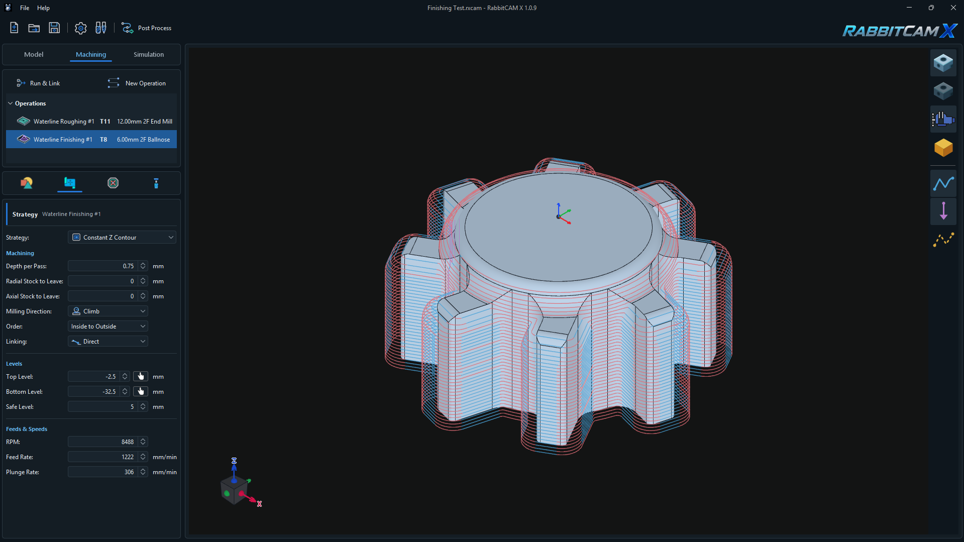
Waterline Finishing follows the contours of a 3D part at successive Z levels using the Constant Z Contour strategy. It is useful for finishing walls and steep regions after roughing.
The example above uses T8 — 6.00 mm 2F Ballnose, a 0.75 mm Depth per Pass, zero radial and axial allowances, Climb milling, and Direct linking. It follows a Waterline Roughing operation in the Operations tree.
The finishing paths are calculated from the Part geometry. They are not trimmed to the stock remaining from earlier operations. Prepare the material with appropriate roughing operations, then inspect the complete sequence in Simulation.
For the preceding operation, see Waterline Roughing.
Creating the Operation and Selecting Surfaces
- Prepare the 3D part, work zero, and Work Holding, and place the required roughing operations before finishing.
- Open Machining > New Operation and select Waterline Finishing under 3D Operations.
- Review the operation name and assigned milling tool, then click Create.
- Select the operation and open Job Assignment.
- Use Pick > Surface or Surfaces (Lasso) to select the surfaces to finish, then click Finish Surface Selection.
Connected selected surfaces are organized into Surface Groups. Include the walls and curved surfaces that should receive finishing passes, and review the highlighted geometry.
If Job Assignment is empty, the operation derives contours from the whole Part within the requested depth range and applicable restrictions. Selecting surfaces limits the finishing scope to those surfaces.
The operation supports End Mill, Ball Nose, Bull Nose, and Tapered Ball Nose tools. The generated tool-center paths account for the assigned cutter profile, so recalculate after changing the tool.
Constant Z Contour and Depth per Pass
Each cutting contour lies at a constant Z height. The operation works down through the requested depth range, with Depth per Pass controlling the maximum vertical distance between successive levels.
The screenshot uses 0.75 mm. A smaller value creates more closely spaced levels and can reduce the marks left between passes, at the cost of more toolpath and machining time. A smaller final step is used when necessary to reach Bottom Level.
Constant Z spacing is vertical spacing, not a constant distance measured along the part surface. On shallow slopes, adjacent contours can be farther apart across the surface than they are on steep walls.
Inspect shallow and horizontal areas separately in Simulation. Contour finishing does not provide a complete area-clearing pass across a flat face; add an appropriate operation where further coverage is needed.
Radial and Axial Stock to Leave
- Radial Stock to Leave retains material on steep and vertical part walls.
- Axial Stock to Leave retains material above horizontal and sloped part surfaces.
Both values are 0 mm in the example, requesting no additional finishing allowance in either direction.
Use positive values when this operation should leave material for a later pass. The values are independent directional allowances; they are not added together into one uniform offset.
Zero allowance does not guarantee that every surface is fully finished. Cutter shape, access, the selected surfaces, and the spacing between Z levels determine the actual coverage. Check the remaining material after simulation.
Milling Direction and Contour Order
Milling Direction selects Climb or Conventional for the cutting contours. The screenshot uses Climb.
Order controls the sequence of independent contours within each Z level:
- Inside to Outside processes the inner or smaller contours first.
- Outside to Inside processes the outer or larger contours first.
The example uses Inside to Outside. This setting changes contour order within the operation; the Operations tree determines when the finishing operation runs relative to other operations.
When several surface targets are present, the operation completes the requested Z levels for one target before moving to the next.
Linking: By Safe Level or Direct
Linking controls how the tool travels between successive contours.
- By Safe Level retracts to the calculated clearance height, moves across to the next contour, and feeds down to its start using Plunge Rate.
- Direct attempts a checked connection within the same surface target without returning to Safe Level for every contour. It may move along part of the preceding contour, including backtracking, to reach a suitable connection point.
If the Direct connection or the required movement along the preceding contour fails the clearance checks, RabbitCAM X uses By Safe Level for that transition.
The screenshot uses Direct. Approach, retract, and fallback moves still use clearance height, so Safe Level remains relevant. Review the linking moves as well as the cutting contours in Simulation.
Clearance checks use the modeled geometry. Since finishing paths do not use remaining stock to limit their scope, inspect the result together with the preceding roughing operations.
Setting the Machining Levels
The level values are Z coordinates relative to the project's work zero:
- Top Level — the upper reference for the finishing depth range.
- Bottom Level — the requested final Z level. It must not be above Top Level.
- Safe Level — the minimum clearance height used for approaches, retracts, and connections through clearance. It must be above Top Level.
The screenshot uses Top Level = -2.5 mm, Bottom Level = -32.5 mm, and Safe Level = 5 mm. Review the upper limit when you also need to finish features above this range.
The pick buttons beside Top Level and Bottom Level obtain the selected surface's highest and lowest Z respectively, converted to work coordinates. The calculated clearance height may be raised above the entered Safe Level to clear modeled Part or Work Holding geometry.
For origin setup, see Setting the Workpiece Coordinate System.
Feeds and Speeds
- RPM sets spindle speed in revolutions per minute.
- Feed Rate sets the cutting speed along the contours in mm/min.
- Plunge Rate sets the entry feed from clearance and is also used for near-vertical Direct linking moves.
The example uses 8488 RPM, 1222 mm/min Feed Rate, and 306 mm/min Plunge Rate. Plunge Rate remains editable with Direct selected.
Movement along a preceding contour uses Feed Rate. Direct connections close to the Z direction use Plunge Rate, while more lateral connections use Feed Rate.
These values belong to the pictured project. Choose values for the actual cutter, material, machine, and material left by roughing.
Generating and Checking the Finishing Toolpath
- Confirm the selected surfaces, assigned tool, depth range, allowances, and any Restricted Areas or Work Holding.
- Click Run & Link and select the finishing operation to inspect the generated contours.
- Check coverage near the top and bottom of the selected range, around small features, and across changes in slope.
- Open Simulation and review the roughing and finishing sequence, including entry moves, Direct connections, clearance moves, and material remaining between passes.
- Adjust Depth per Pass or add further operations where the required surface coverage is not achieved. Recalculate after changes to geometry, assignments, tools, parameters, or fixture placement.
- Save with Ctrl+S and use Post Process when the setup is ready.
If the operation reports that the selected Part scope contains no machinable Constant Z contour, check the selected surfaces, the Z range, tool access, and protected areas. Selecting only a flat surface may not produce the wall contours you intended to finish.
If Direct linking still produces retracts, review the geometry around those transitions: the operation falls back to Safe Level when a checked direct connection is unavailable.