
Waterline Roughing
Remove stock around a 3D part in successive Z layers using Adaptive Contour or ZigZag, with separate radial and axial allowances for finishing.
Waterline Roughing Overview
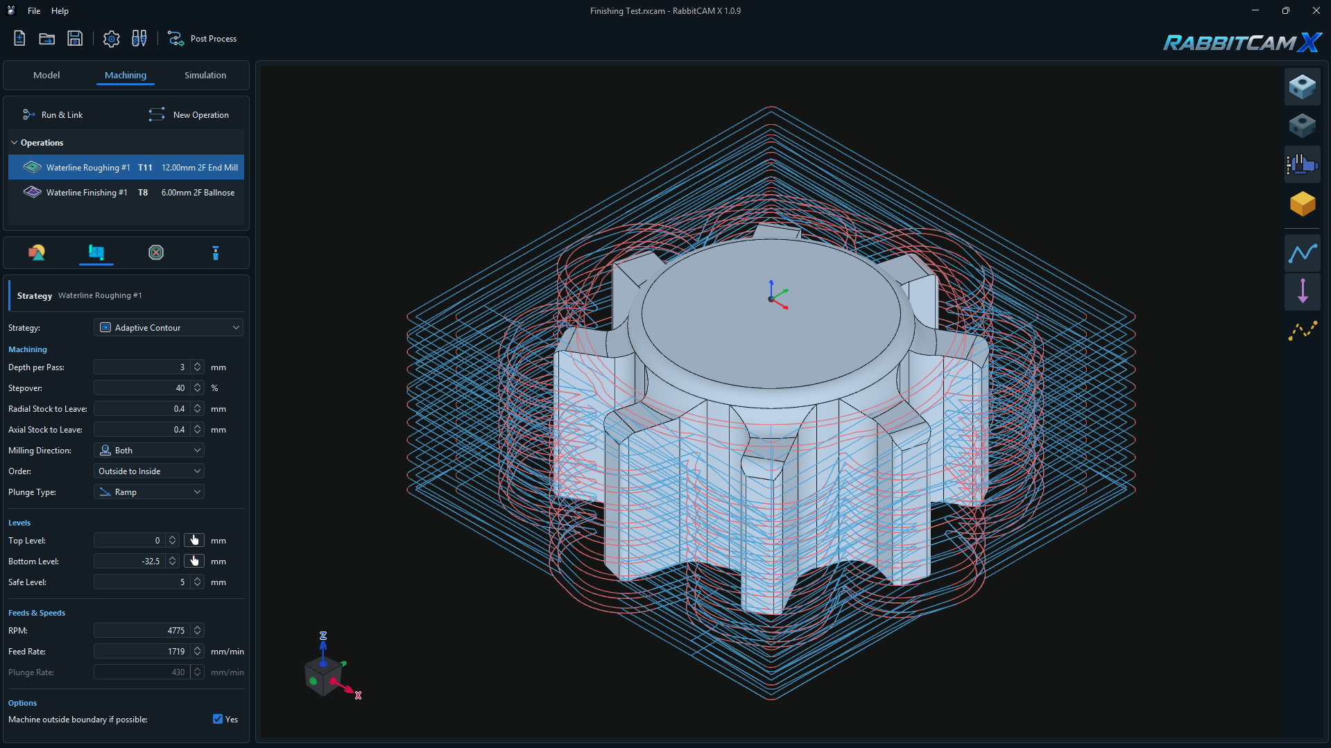
Waterline Roughing removes stock around a 3D part in successive Z layers. The toolpath accounts for the part geometry, the remaining stock from preceding operations, and the selected machining region.
Use this operation to remove bulk material before finishing. Separate Radial Stock to Leave and Axial Stock to Leave settings let you retain material on walls and above surfaces.
The example above uses Adaptive Contour with T11 — 12.00 mm 2F End Mill, a 3 mm Depth per Pass, 40% Stepover, and 0.4 mm for both allowances. A separate Waterline Finishing operation follows it in the Operations tree.
Creating the Operation and Assigning Geometry
- Prepare the 3D part, stock, work zero, and any Work Holding in Model.
- Open Machining > New Operation and select Waterline Roughing under 3D Operations.
- Review the operation name and assigned milling tool, then click Create.
- Select the operation and open Job Assignment. Use Pick to select geometry and complete the selection using the corresponding finish-selection button in the 3D view.
Surface and Surfaces (Lasso) define targets from selected part surfaces. Boundary selects a closed CAD boundary, while Curves builds a closed chain. Boundary and curve selections must form continuous, closed regions.
When only boundaries or closed curve chains are assigned, they define the machining regions. When surfaces and boundaries are assigned together, the surfaces define the targets and the boundaries further limit the machining area.
If Job Assignment is empty, the operation uses the stock extent as its target while protecting the 3D part and other restricted geometry. Assign geometry when you want to limit roughing to specific areas, and review the highlighted selection before calculating.
Choosing Adaptive Contour or ZigZag
- Adaptive Contour generates contour-based passes for the available region and remaining material. Order selects Inside to Outside or Outside to Inside. Milling Direction offers Both, Climb, and Conventional.
- ZigZag generates parallel passes in alternating directions. Orientation selects Horizontal, parallel to X, or Vertical, parallel to Y. Milling Direction is fixed to Both.
The screenshot uses Adaptive Contour, Outside to Inside, and Both. The Order field controls the generated contours within this operation. The Operations tree controls the sequence of separate operations.
After changing strategy, review the available direction and pattern settings again.
Depth per Pass and Stepover
- Depth per Pass is the maximum vertical step between cutting layers. A smaller final step is used when the requested depth is not an exact multiple of this value.
- Stepover is the target lateral advance between adjacent cutting passes, expressed as a percentage of tool diameter.
The example uses 3 mm Depth per Pass and 40% Stepover. With a 12 mm tool, 40% corresponds to a nominal 4.8 mm lateral advance. Actual paths depend on the available stock, part shape, and protected regions.
Smaller depth steps leave finer terraces on sloped surfaces. Stepover controls lateral pass spacing; it does not set the height of those terraces.
Radial and Axial Stock to Leave
These two settings control the material intentionally retained for subsequent finishing:
- Radial Stock to Leave retains material on steep and vertical part walls.
- Axial Stock to Leave retains material above horizontal and sloped part surfaces.
The screenshot sets both values to 0.4 mm. They are separate directional allowances, not values to add into a single 0.8 mm allowance.
A value of 0 mm requests no additional allowance in that direction. It does not guarantee a finished surface: layer spacing, cutter shape, and inaccessible regions can leave additional material.
Choose the allowances for the finishing operation that will follow. Inspect the simulated stock after roughing to see what remains around walls, on sloped areas, and in corners.
Setting the Machining Levels
The levels use Z coordinates relative to the project's work zero:
- Top Level — the starting height for the machining depth range.
- Bottom Level — the requested lowest cutting level. It must not be above Top Level.
- Safe Level — the clearance height for approach, linking, and retract moves. It must be above Top Level.
The pictured setup uses Top Level = 0 mm, Bottom Level = -32.5 mm, and Safe Level = 5 mm. These define the requested depth and clearance; part protection and allowances determine where cutting can actually take place.
For a surface-based target, the effective bottom is the higher of the entered Bottom Level and the lowest point of its selected surfaces. Selecting only an upper surface can therefore limit the depth even if you enter a lower Bottom Level.
The pick buttons beside Top Level and Bottom Level obtain the selected surface's highest and lowest Z respectively, converted to work coordinates. For origin setup, see Setting the Workpiece Coordinate System.
Plunge Type and Feeds and Speeds
- Straight enters a cutting layer with a vertical feed move.
- Ramp lowers the tool progressively along a suitable cutting path. The path may be repeated or traversed back and forth to provide the required entry length.
If a suitable ramp cannot be formed, the original straight plunge is retained. Review the generated entries in Simulation.
RPM sets spindle speed. Feed Rate sets cutting feed in mm/min. Plunge Rate sets the feed for straight downward entry moves.
With Ramp selected, the Plunge Rate field is disabled and generated ramp moves use the cutting-path feed. In this screenshot, the operation uses 4775 RPM and 1719 mm/min Feed Rate; the displayed 430 mm/min Plunge Rate is not editable while Ramp is selected.
These are the example project's settings. Set the operating values for your cutter, material, machine, and engagement.
Machine Outside Boundary if Possible
This option controls whether the tool center can move beyond the assigned machining boundary where stock is available.
- Enabled — permits movement beyond the boundary where the stock, part geometry, and protected regions allow it.
- Disabled — keeps the tool-center region within the machining boundary, including the required tool-radius and allowance offset.
The screenshot has this option enabled. Part protection, Restricted Areas, and Work Holding remain part of the calculation. Check paths near boundary edges and adjacent features after changing this option.
Generating the Toolpath and Preparing for Finishing
- Review Job Assignment, the selected tool, the depth range, both allowances, and any Restricted Areas.
- Click Run & Link, then select the roughing operation to inspect its toolpaths.
- Check the layer coverage, entry moves, paths around the part, and motion near fixtures. The calculated clearance height may be raised above Safe Level to clear modeled part or Work Holding geometry.
- Open Simulation and inspect the stock remaining after roughing, especially around steep walls, sloped surfaces, and narrow features.
- Place the required finishing operations after roughing and review the combined result. Recalculate after changing geometry, tools, parameters, stock, or fixture placement.
- Save the project with Ctrl+S and use Post Process when the setup is ready.
If roughing stops higher than expected, check the lowest point of the assigned surfaces, Bottom Level, and axial allowance. If little or no material is removed, review the stock remaining from earlier operations, the assigned region, tool size, and protected geometry.
For fixture setup, see Setting Up Work Holding.