Scallop 3D
Finish 3D surfaces with the Spiral strategy, controlling surface pass spacing, radial and axial allowances, entry preference, and machining direction.
Scallop 3D Overview
Scallop 3D finishes 3D surfaces using the Spiral strategy. It builds successive passes along the selected surfaces, accounts for the cutter shape, and connects neighboring passes where the geometry allows.
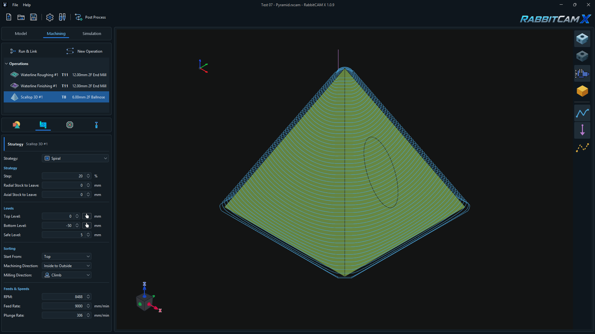
The example above uses T8 — 6.00 mm 2F Ballnose to finish a pyramid-shaped part. Its settings include Step = 20%, zero radial and axial allowances, Start From = Top, Machining Direction = Inside to Outside, and Milling Direction = Climb.
The operation calculates its paths from the Part geometry and selected surfaces. Remaining stock from preceding operations does not limit the finishing paths. Prepare the material with appropriate roughing operations and inspect the complete sequence in Simulation.
The pictured project places Scallop 3D after Waterline Roughing and Waterline Finishing.
Creating the Operation and Assigning Surfaces
- Prepare the 3D Part, stock, Workpiece Coordinate System, and any Work Holding.
- Open Machining > New Operation and select Scallop 3D under 3D Operations.
- Review the operation name and assigned milling tool, then click Create.
- Select the operation and open Job Assignment.
- Use Pick > Surface or Surfaces (Lasso) to select the surfaces to finish, then click Finish Surface Selection.
Connected selected surfaces are organized into Surface Groups. Review the highlighted geometry to confirm that the intended faces are included.
You can also assign a Boundary or use Curves to form a closed, continuous machining limit. These limits restrict the surface contact area in the work-coordinate XY plane. The tool-center path can extend beyond that contact boundary because of the cutter's shape and radius.
If no surfaces are assigned, RabbitCAM X derives targets from the Part objects, subject to any assigned machining limits, depth limits, and restrictions.
Supported tools include End Mill, Ball Nose, Bull Nose, and Tapered Ball Nose. Verify the assigned tool geometry and recalculate after changing it.
Step and Surface Pass Spacing
Step controls the maximum distance between neighboring passes measured along the surface, expressed as a percentage of the tool's nominal cutting diameter.
For the pictured 6 mm tool at 20%, the corresponding surface step is:
6 mm × 20 / 100 = 1.2 mm
The allowed value is greater than zero and up to 100%. Changing the tool diameter changes the distance represented by the same percentage.
A smaller Step creates more closely spaced passes and generally reduces the ridges left between them, while increasing toolpath length and calculation time. The resulting finish also depends on cutter shape, local curvature, and access to the surface.
Step specifies surface spacing. It does not specify a fixed vertical depth increment or a guaranteed scallop height. Judge the result from the generated paths and the remaining material in Simulation.
Radial and Axial Stock to Leave
- Radial Stock to Leave retains material on steep and vertical Part surfaces.
- Axial Stock to Leave retains material above horizontal and sloped Part surfaces.
Both values are 0 mm in the screenshot, requesting no additional allowance in either direction.
Use positive allowances when this operation should leave material for another finishing pass. The two values control different directions and are not added into one uniform offset.
Zero allowance does not guarantee complete finishing everywhere. Pass spacing, cutter shape, selected geometry, and inaccessible areas can leave additional material. Inspect corners and changes in surface slope after simulation.
Setting the Machining Levels
These values use Z coordinates relative to the project's work zero:
- Top Level — the highest tool-tip level included in finishing.
- Bottom Level — the lowest tool-tip level included in finishing. It must not be above Top Level.
- Safe Level — the minimum clearance height used between independent paths. It must be above Top Level.
The example uses Top Level = 0 mm, Bottom Level = -50 mm, and Safe Level = 5 mm.
The limits apply to the tool tip. With a shaped cutter such as a ballnose, the point touching the surface can be at a different height from the tool tip.
Use the pick buttons beside Top Level and Bottom Level to obtain the selected surface's highest and lowest Z respectively, converted to work coordinates, then review the resulting toolpath coverage.
For origin setup, see Setting the Workpiece Coordinate System.
Sorting: Start From and Machining Direction
The Sorting section provides three controls:
- Start From — Top prefers the highest accessible tool-tip entry, while Bottom prefers the lowest accessible entry among the starts allowed by Machining Direction.
- Machining Direction — Inside to Outside progresses outward through the surface passes; Outside to Inside progresses inward from the boundaries.
- Milling Direction — selects Climb or Conventional for the cutting paths.
The screenshot uses Top, Inside to Outside, and Climb.
Start From is an entry preference within the permitted path order and accessible geometry. Selecting Bottom does not require the first entry to lie exactly at Bottom Level. Top Level and Bottom Level continue to define the machining limits.
Recalculate after changing these controls and inspect both the entry position and the progression of the passes.
Feeds and Speeds
- RPM sets spindle speed in revolutions per minute.
- Feed Rate sets movement speed along the cutting paths in mm/min.
- Plunge Rate sets the downward feed used to enter independent paths from clearance.
The pictured project uses 8488 RPM, 9000 mm/min Feed Rate, and 306 mm/min Plunge Rate.
These are the settings of this example. Choose operating values for the actual cutter, material, machine, and material left by the preceding operations.
Path Connections and Protected Geometry
The Spiral strategy attempts smooth connections between neighboring passes in the same connected region while preserving the cutting direction. When a suitable checked connection is unavailable, the paths remain separate and are linked through clearance height.
Restricted Areas limit the permitted machining area. Modeled Work Holding is included in checks of the cutting paths and connecting moves. Review fixture placement and the assigned tool geometry before generating the operation.
The calculated clearance height can be higher than the entered Safe Level to clear the Part, Work Holding, and other relevant path positions.
A single operation can therefore contain several separate paths and retracts. Inspect those transitions in Simulation, particularly near holes, separated surface groups, narrow features, and fixtures.
Generating and Checking the Scallop Toolpath
- Review the selected surfaces, machining boundaries, Restricted Areas, tool, Step, allowances, and levels.
- Click Run & Link and select the Scallop 3D operation to display its paths.
- Check surface coverage, spacing around changes in curvature, the chosen entry, and the direction in which the passes progress.
- Open Simulation and review the preceding operations together with Scallop 3D. Inspect remaining material, entries, connections, and clearance moves.
- Adjust Step or the machining scope where further coverage is needed. Recalculate after changing geometry, assignments, tools, parameters, stock, or fixture placement.
- Save with Ctrl+S and use Post Process when the setup is ready.
If no accessible cutter paths are produced, check the selected surfaces, tool geometry and reach, Top/Bottom Levels, machining limits, and protected regions. If an entry cannot be found, review the available approach to the selected region and the Sorting settings.
If a saved surface assignment no longer matches the current Part, reselect the intended surfaces before recalculating.